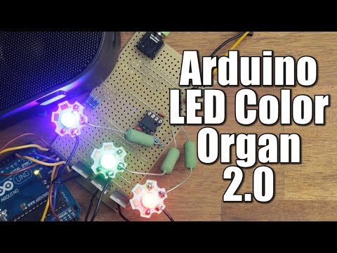
Hi, this is Wayne again with a topic “Weekend Projects – Easy LED Color Organ”.
Hi, I’m Eric wine offer product development engineer with make if you enjoy music and blinky lights and who doesn’t and you’ll really enjoy this project. When Colin Cunningham published his fancy, LED color organ and makes circuit skills, video series, one reader, was inspired to build a simpler circuit to achieve the same goal. Akhi, the LED artist designed this bare-bones version that works great and uses only about thirty components, plug your music into this project and the circuit divides the sound into high, mid and low frequencies and then flashes three different colors of LEDs according to the different frequencies. It’S like a little disco light on your desktop by using these parts and following the instructions on the project page.

This build can be completed in less than an hour with no soldering required. The circuit is broken into four parts. The audio input takes the audio from your music player.
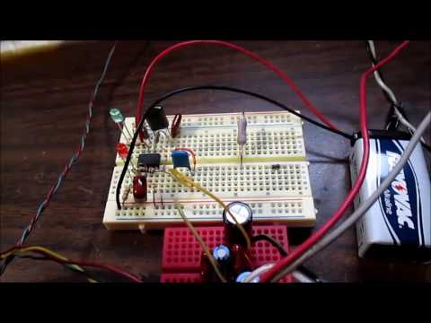
The high frequency filter blinks the blue LEDs when high-frequency tones play the mid frequency filter, blinks the green LEDs when mid frequency tones play and the low frequency filter, blinks the red LEDs when low frequency tones play to begin, install, jumper wires to connect the power and Ground rails on opposite sides of the breadboard and connect the 9-volt battery clip. This will provide power and ground all across the board. Insert a 10 kilo, ohm resistor from the power rail to an arbitrary row. Remember, resistors aren’t polarized, so it doesn’t matter what orientation you insert it in insert the 2n3 904 transistor into the breadboard, with the flat side facing toward the center trough of the breadboard.

Looking at it in this orientation, the left leg is called the emitter, the middle leg, the base and the right leg. The collector connect the ground rail to the leftmost pin of the transistor. The emitter with a jumper insert the second 10 kilo ohm resistor, connecting the first resistor to the base of the transistor connect, a 1 kilo ohm resistor from the power rail to the transistors rightmost pin the collector then connect the diode from the 2 10 kilo ohm Resistors to the leftmost pin of the transistor, noting its polarity, the diodes black stripe should be nearest. The transistor connect the 10 micro farad capacitor from the base of the transistor to the other side of the breadboard. Again, noting the polarity, the positive side without the black stripe should be connected to the transistor connect 2 100 ohm resistors to the negative leg of the capacitor and insert their other legs into two separate rows.
These are where the left and right audio inputs will connect. Use alligator clips to attach jumper wires to the three legs of the audio jack or you can solder them on directly. The ground goes directly to the ground rail on the breadboard. The other two pins are for the left and right audio inputs connect each one to one of the 100 ohm resistors. It doesn’t matter which your audio input is now ready.
Next you’ll build the high frequency filter. This part of the circuit works by filtering out all the low frequencies of the audio spectrum and only allowing the high frequencies to pass through and trigger the LEDs insert a 2 n 3 906 transistor into the breadboard, with its flat side facing forward again and connect Power to its emitter leg, the left one with a jumper connect power to the base of the transistor. With a 2 point, 2 kilo, ohm resistor insert the 0.47 micro farad capacitor into the board, connecting one leg to the base of the transistor and the other to an arbitrary spot. On the other side of the breadboard /, the trough connect the other leg of the capacitor to the collector of the 2 n 3 904 transistor, with a jumper wire connect, the positive leg of a blue, the longer leg to the collector of the transistor hookup, a 100 ohm resistor from the negative leg of the led over the trough to the other side of the board connect. The second blue LED it’s positive leg to the 100 ohm resistor and it’s negative leg to ground now build the mid frequency filter by changing the values of the components we are able to filter out all the high and low ends of the audio spectrum and only Allow the mid-range signals to pass through the circuit insert another two and three 906 transistor into the breadboard, with the flat side facing forward again connect the emitter of the transistor to the power rail with a jumper wire connect, the base of the transistor to the power Rail with a two point, two kilo, ohm resistor hookup, the point: zero 1 microfarad capacitor between the base and emitter legs of the transistor polarity, doesn’t matter with a ceramic capacitor, now connect the positive leg of the big point for seven micro farad cap to the base Of the transistor and the negative leg across the trough of the breadboard connect a 1 kilo, ohm resistor from the negative leg of this big cap to the hub. The positive leg of the second blue LED you installed earlier.
The three filters will all connect at this point: connect a green LEDs, positive leg to the rightmost leg. The collector of the transistor connect the 180 ohm resistor from the negative leg of the LED across the trough insert the second green LED into the breadboard. It’S positive leg to the 180 ohm resistor and it’s negative leg to ground finally build the low frequency filter in the last filter. We again change a few variables that allow only the low frequencies to pass through the circuit and trigger the LEDs, insert a to n3 906 transistor into the breadboard, with the flat side facing the trough, as before connect power to the emitter leg of the transistor.
With a jumper connect, a 2.2 kilohm resistor from the power rail to the base of the transistor insert the 1 micro farad capacitor, with its negative leg connected to the base of the transistor, and it’s positive leg connected to the emitter connect. Another 2.2 kilohm resistor across the trough of the breadboard, from the negative leg of the 1 micro farad cap to an arbitrary spot on the board, connect this resistor back to the hub with a long jumper wire. This connects the low frequency sub circuit to the rest. Insert a red LED with its positive leg, connected to the collector of the transistor and then connect a 270 ohm resistor across the trough to its negative lead, connect. The second red LED it’s positive like to the 270 ohm resistor and it’s negative leg to ground, and that’s it plug one of the male ends of the audio splitter into the audio jack of the color organ and plug the other male end into your music player. Now plug your speakers or headphones into the female end of this player, plug in the battery and start pumping the tunes the LED color organ listens to your music and splits.
It into three frequency ranges using the filters you just built. The red LEDs will flash in time with the bass frequencies, the green LEDs will flash to the middle range and the blue LEDs will flash to the high treble notes. One good test is to play bass, heavy music and see how well your LED color organ shakes.
Its booty we’d love to hear your experiences share your build notes, photos and mods with us at the project. Page .